FTTH Network Deployment: From Central Office to Subscriber Premises
FTTH Network Deployment: From Central Office to Subscriber Premises
Published: 2026-05-20
Understanding FTTH Architecture
Fiber-to-the-Home (FTTH) represents the gold standard of broadband access — delivering fiber optic connectivity directly to individual residences and businesses. Unlike FTTB (Building) or FTTC (Curb), FTTH eliminates all copper in the last mile, enabling gigabit+ speeds with future scalability to multi-gigabit services.
A complete FTTH network consists of three major segments:
1. Feeder Network (Central Office to FDH)
The feeder segment begins at the Central Office (CO) with the Optical Line Terminal (OLT) and extends to the Fiber Distribution Hub (FDH), typically located in a street cabinet or outdoor enclosure. Feeder cables are high-fiber-count (144-288 fibers) and use outdoor-rated loose tube construction.
2. Distribution Network (FDH to FDT)
From the FDH, the signal passes through optical splitters (typically 1:8, 1:16, or 1:32 split ratios) and travels via distribution cables to Fiber Distribution Terminals (FDTs) closer to subscriber clusters. This segment typically uses 12-48 fiber cables.
3. Drop Network (FDT to Subscriber)
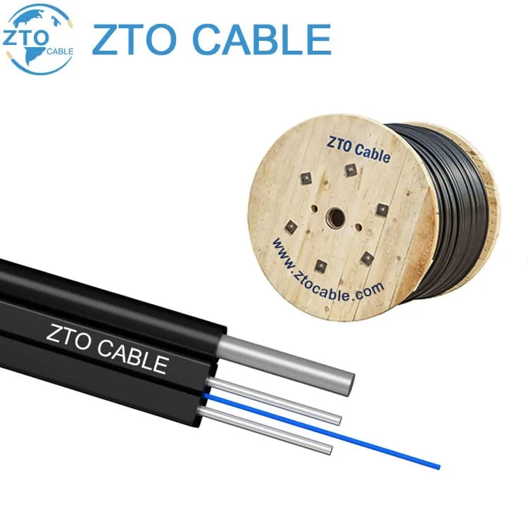
The final segment — the “last mile” — connects the FDT to individual subscriber premises using drop cables. This is where the GJXCH and GJXFH cables come into play.
FTTH Network Topologies
GPON (Gigabit Passive Optical Network)
The dominant FTTH standard worldwide, specified by ITU-T G.984:
- Downstream: 2.488 Gbps (shared across 32-64 users per PON port)
- Upstream: 1.244 Gbps
- Maximum reach: 20km (logical), 60km with range extenders
- Split ratio: Up to 1:128 (1:64 typical)
XGS-PON (10G Symmetrical)
The next-generation standard for new deployments:
- Downstream/Upstream: 10 Gbps symmetrical
- Backward compatible with GPON on same ODN
- Split ratio: Up to 1:256
Key FTTH Components
Central Office (CO) Equipment
- OLT (Optical Line Terminal): Terminates the PON protocol, manages ONUs, provides uplink to metro/core network
- ODF (Optical Distribution Frame): High-density fiber termination, patching, and management
Outside Plant (OSP) Components
| Component | Function | Typical Location |
|---|---|---|
| FDH (Fiber Distribution Hub) | Houses optical splitters, feeder/distribution cross-connect | Street cabinet |
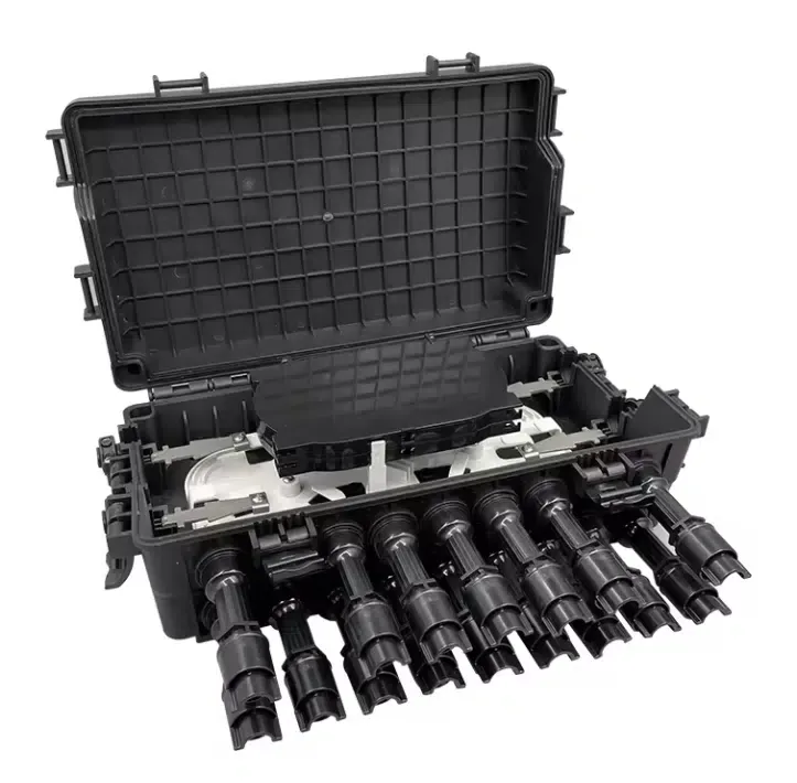
| FDT (Fiber Distribution Terminal) | Distribution-to-drop interface point | Pole or pedestal |
| FAT (Fiber Access Terminal) / NAP | Drop cable connection point near subscriber | Pole, wall, or underground |
| Splitter (1:N) | Divides optical signal among N subscribers | FDH or FDT |
Subscriber Premises Equipment
- ONT/ONU (Optical Network Terminal/Unit): Converts optical signal to electrical (Ethernet, WiFi, POTS)
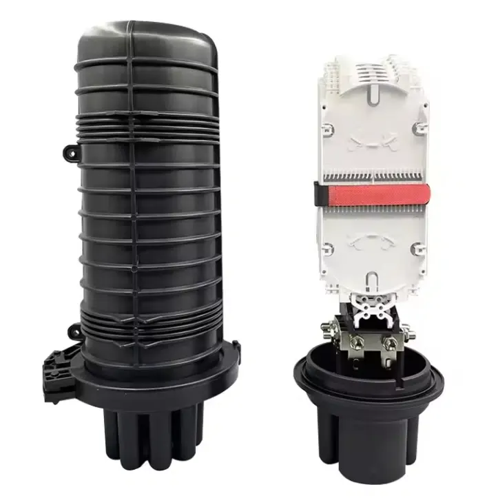
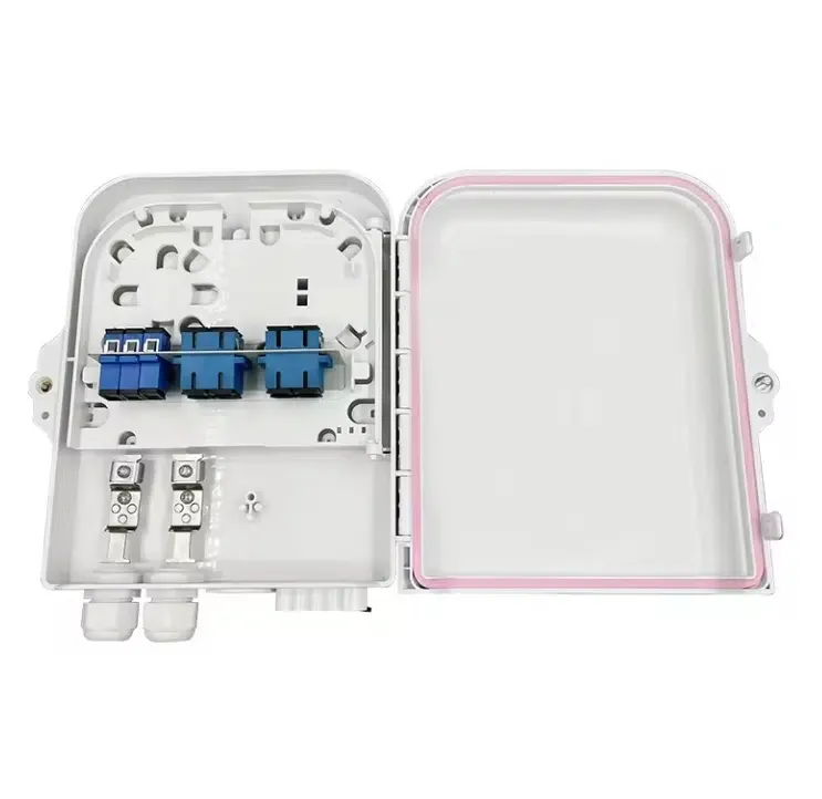
- FTTH Terminal Box: Indoor or outdoor enclosure for fiber termination and connector interface
Drop Cable Selection
The drop cable is the subscriber’s physical connection to the network. Key considerations:
GJXCH (with Steel Wire Messenger)
- Aerial drops between poles
- Self-supporting — no separate messenger needed
- Higher tensile strength
- Ideal for overhead suburban/rural deployments
GJXFH (without Steel Wire)
- Underground drops through ducts
- Lighter and more flexible
- Lower cost (no steel wire)
- Ideal for urban ducted deployments
Bend Radius Considerations
FTTH drop cables experience tight bends in residential routing — through walls, around corners, inside termination boxes. Always specify G.657.A2 bending-insensitive fiber for FTTH drops to ensure reliable performance with bend radii as tight as 7.5mm.
Splitter Placement Strategy
Where you place the optical splitter has a major impact on fiber utilization and cost:
Centralized Splitting (1-stage)
- Splitter at FDH (feeder/distribution boundary)
- Each subscriber gets a dedicated fiber from splitter to premises
- Advantage: Simple management, easy troubleshooting
- Disadvantage: High fiber count in distribution network
Distributed Splitting (2-stage)
- First split at FDH, second split at FDT or FAT
- Shared distribution fibers between splitter stages
- Advantage: Higher fiber utilization, lower cable cost
- Disadvantage: More complex network planning and optical budget management
Recommended Approach
Use centralized splitting for low-density rural areas (simpler logistics). Use distributed splitting for high-density urban areas (better fiber utilization). Many operators use a hybrid approach with 1:4 at FDH + 1:8 at FDT for optimized 1:32 total split.
Installation Best Practices
Aerial Drop Installation
- Maintain proper sag between poles (1-2% of span length)
- Use proper dead-end grips and drop wire clamps
- Provide drip loops at building entry points
- Avoid contact with tree branches and other utilities
- Minimum clearance from power lines: follow local electrical code (typically 40cm for telecom)
Underground Drop Installation
- Use HDPE microducts for flexibility and protection
- Minimum burial depth: 30-45cm for residential, 60cm for road crossings
- Install tracer wire for future locate capability
- Leave service loops (5-10m) at both ends for future maintenance
- Seal duct ends to prevent water and pest ingress
Optical Budget Planning
A critical step in FTTH design is calculating the optical power budget:
| Loss Element | Typical Value |
|---|---|
| Fiber attenuation (G.652D @ 1490nm) | 0.30 dB/km |
| Splice loss (fusion) | 0.05 dB per splice |
| Connector loss | 0.3 dB per mated pair |
| 1:32 splitter loss | 17.0 dB |
| 1:64 splitter loss | 20.5 dB |
| Safety margin | 3.0 dB |
Example budget for 20km reach with 1:32 split:
- Fiber: 20km × 0.30 = 6.0 dB
- Splices: 8 × 0.05 = 0.4 dB
- Connectors: 4 × 0.3 = 1.2 dB
- Splitter: 1:32 = 17.0 dB
- Margin: 3.0 dB
- Total: 27.6 dB (well within GPON Class B+ budget of 28 dB)
Testing and Commissioning
Before declaring an FTTH installation complete:
- OTDR testing on feeder and distribution segments — verify no unexpected losses or breaks
- OLTS (Optical Loss Test Set) end-to-end measurement — confirm within optical budget
- Connector end-face inspection — clean and inspect every connector (IEC 61300-3-35)
- ONT registration — verify ONT is recognized by OLT and receiving expected signal level
Future-Proofing Your FTTH Network
- Deploy G.657.A2 fiber everywhere — backward compatible with G.652.D but with bend tolerance for future indoor applications
- Install empty microducts alongside active cables — enables future cable additions without re-trenching
- Plan for XGS-PON — design optical budget for 10G (requires slightly better signal quality at higher bitrates)
- Consider 5G small cell backhaul — FTTH network infrastructure can serve double duty for wireless backhaul
Frequently Asked Questions
What is the difference between GPON and XGS-PON?
GPON (ITU-T G.984) provides 2.5 Gbps downstream / 1.25 Gbps upstream shared across 32-64 users per PON port. XGS-PON (ITU-T G.9807.1) provides 10 Gbps symmetrical and is backward-compatible with GPON on the same ODN fiber infrastructure. Most new FTTH deployments choose XGS-PON to future-proof the network, even if GPON line cards are used initially.
How far can FTTH fiber reach from the central office?
Standard GPON reach is 20 km (logical distance, accounting for splitter loss). With Class B+ or C+ optics and careful optical budget planning, 30-40 km is achievable. For rural deployments, range extenders (optical amplifiers or OEO regenerators) can push reach to 60+ km. The practical limit is usually determined by subscriber density and splice loss accumulation rather than pure optical budget.
What split ratio should I use: 1:16, 1:32, or 1:64?
1:32 is the most common balance, providing 32 subscribers per PON port with sufficient optical budget margin. 1:64 offers higher port utilization but reduces per-subscriber bandwidth and requires tighter optical budget engineering. For rural/low-density areas, 1:16 or even 1:8 provides more margin. For dense urban, 1:64 with XGS-PON is viable.
How do I protect outdoor FTTH enclosures from water damage?
All outdoor FTTH enclosures (FDH, FDT, NAP/CTO) should be rated IP65 or higher. Gel-filled splice closures and heat-shrink sealed cable entries prevent water ingress at cable entry points. For below-grade (underground) enclosures, IP68 rating is required. Regular inspection of door gaskets and cable entry seals prevents moisture accumulation over time.