
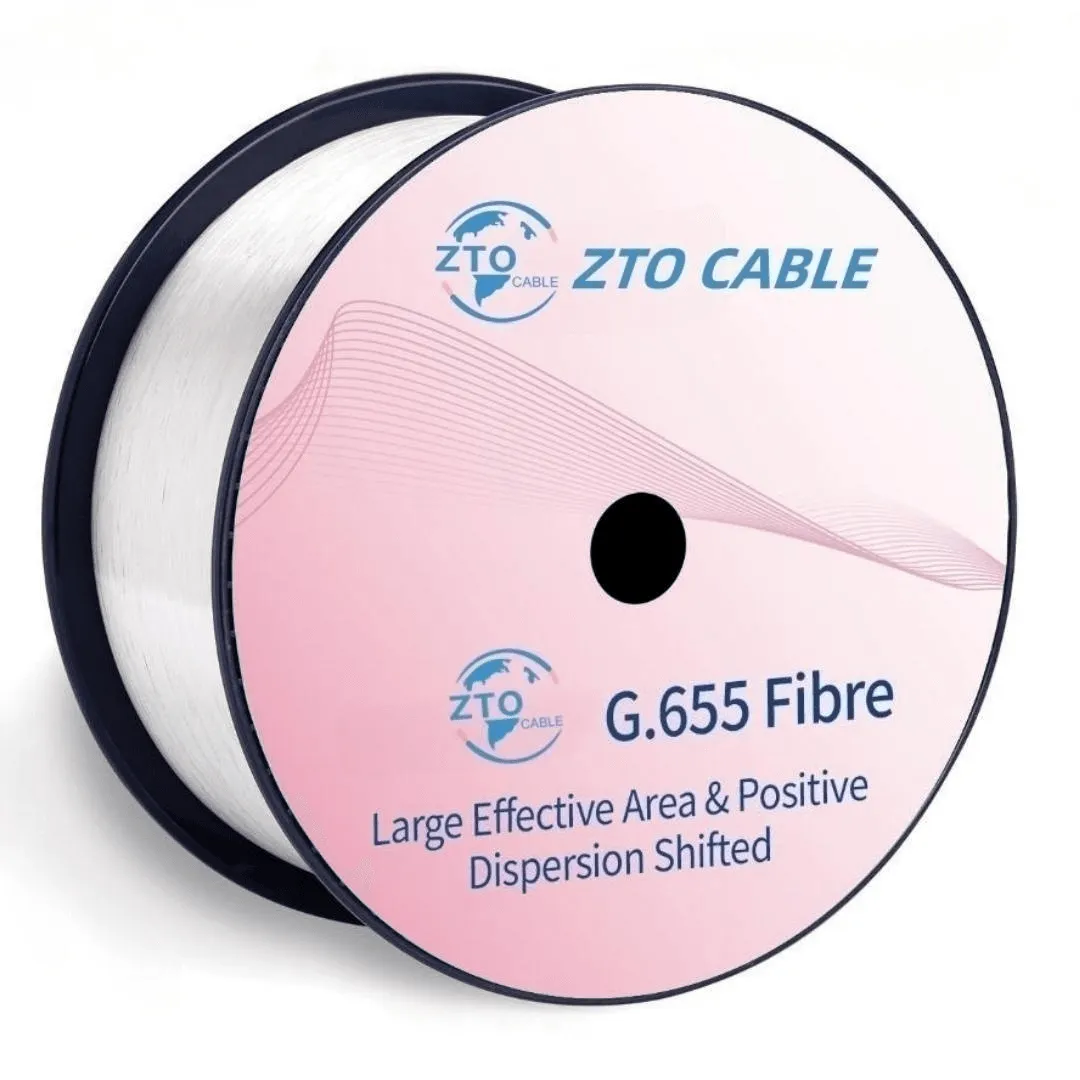
Optical Fiber
Bending Insensitive Single mode optical fiber G655
G.655 non-zero dispersion-shifted fiber (NZ-DSF) is engineered for long-haul DWDM transmission systems. By shifting the zero-dispersion point outside the 1550nm window (C-band), it maintains a small, controlled amount of chromatic dispersion that effectively suppresses four-wave mixing (FWM) — a nonlinear impairment that degrades DWDM signal quality. The large effective area design further reduces nonlinear effects, enabling higher channel counts and longer amplifier spans. Compliant with ITU-T G.655.C/D specifications.
Get the Best PriceZTOFC G.655 fiber (Large Effective Area Non-Zero Dispersion Shifted Single-mode Fiber) is comprehensively optimized for attenuation and dispersion performance at the 1550nm operating wavelength. The fiber delivers the lowest attenuation and moderate dispersion at 1550nm, enabling excellent performance in multi-channel Dense Wavelength Division Multiplex (DWDM) systems operating in the C-band (1530–1565nm) and emerging L-band (1565–1625nm) systems.
Specifications
Optical Characteristics
| Characteristics | Conditions | Specified values | Units |
| Attenuation | 1550nm | ≤0.22 | [dB/km] |
| Attenuation | 1625nm | ≤0.24 | [dB/km] |
| Attenuation vs. WavelengthMax. α difference | 1525-1575nm, in reference to 1550nm | ≤0.02 | [dB/km] |
| Dispersion Coefficient | 1530-1565nm | 2.0-6.0 | [ps/(nm·km)] |
| Dispersion Coefficient | 1565-1625nm | 4.5-11.2 | [ps/(nm·km)] |
| Zero Dispersion Wavelength(λ0) | — | ≤1520 | [nm] |
| Dispersion Slope | 1550nm | ≤0.084 | [ps/(nm2·km] |
| Typical dispersion slope | 1550nm | 0.075 | [ps/(nm2·km] |
| PMD / Maximum Individual Fibre | — | ≤0.2 | [ps/√km] |
| PMD / Link Design Value(M=20,Q=0.01%) | — | ≤0.08 | [ps/√km] |
| PMD / Typical Value | — | 0.04 | [ps/√km] |
| Cable Cutoff Wavelength (λCC) | — | ≤1450 | [nm] |
| Mode Field Diameter(MFD) | 1550nm | 9.1-10.1 | [μm] |
| Effective Group Index of Refraction(Neff ) | 1550nm | 1.469 | — |
| Effective Group Index of Refraction(Neff ) | 1625nm | 1.469 | — |
| Point Discontinuities | 1550nm | ≤0.05 | [dB] |
Geometrical Characteristics
| Characteristics | Specified values | Units |
| Cladding Diameter | 125.0±0.7 | [μm] |
| Cladding Non-Circularity | ≤1.0 | [%] |
| Coating Diameter | 235-250 | [μm] |
| Coating-Cladding Concentricity Error | ≤12.0 | [μm] |
| Coating Non-Circularity | ≤6.0 | [%] |
| Core-Cladding Concentricity Error | ≤0.6 | [μm] |
| Curl(radius) | ≥4 | [m] |
| Delivery Length | Up to 25.2 | [km/reel] |
Environmental Characteristics ( 1550nm & 1625nm )
| Characteristics | Conditions | Specified values | Units |
| Temperature Dependence Induced Attenuation | -60℃ to +85℃ | ≤0.05 | [dB/km] |
| Temperature-Humidity Cycling Induced Attenuation | -10°C to +85°C, 98% RH | ≤0.05 | [dB/km] |
| Watersoak Dependence Induced Attenuation | 23°C, for 30 days | ≤0.05 | [dB/km] |
| Damp Heat Dependence Induced Attenuation | 85°C and 85% RH, for 30 days | ≤0.05 | [dB/km] |
| Dry Heat Aging | 85℃, for 30 days | ≤0.05 | [dB/km] |
Mechanical Specification
| Characteristics | Conditions | Specified values | Units |
| Proof Test | — | ≥9.0 | [N] |
| Proof Test | — | ≥1.0 | [%] |
| Proof Test | — | ≥100 | [kpsi] |
| Macro-bend Induced Attenuation | |||
| 100 Turns Around a Mandrel of 30 mm Radius | 1625nm | ≤0.05 | [dB] |
| 100 Turns Around a Mandrel of 25 mm Radius | 1550nm | ≤0.05 | [dB] |
| 1 Turn Around a Mandrel of 16 mm Radius | 1550nm | ≤0.05 | [dB] |
| Coating Strip Force | typical average force | 1.5 | [N] |
| Coating Strip Force | peak force | 1.3-8.9 | [N] |
| Dynamic Fatigue Parameter(nd) | — | ≥20 | — |
Applications
ZTOFC fiber has the largest effective area in the G.655 series, suitable for high output power Erbium Doped Fiber Amplifier (EDFA) and multi-channel Dense Wavelength Division Multiplex (DWDM). It can be effectively applied in high bit-rate single-channel and multi-channel long-distance digital transmission links even without dispersion compensation.
Characteristics
- Applicable in high bit-rate operation across 1530–1565nm and 1565–1625nm bands
- Large effective area ensures good economic return from the transmission system
- Low attenuation, low dispersion, low PMD and low zero dispersion slope that satisfy the demand of transmission links
- Low bending induced loss at 1550nm and at the more sensitive 1625nm wavelength
Standard
- ITU-T G.655.C/D
- IEC 60793-2-50 B4.c/d
- Parameters tightened beyond standard specifications for customer convenience
Key Features
- Non-zero dispersion in C-band suppresses four-wave mixing (FWM) in DWDM systems
- Large effective area (≥ 72 μm²) — reduced nonlinear effects at high power
- Optimized for C-band (1530–1565nm) and L-band (1565–1625nm) operation
- Low attenuation: ≤ 0.22 dB/km @ 1550nm
- Low PMD ≤ 0.1 ps/√km — supports 40G/100G channels
- Compliant with ITU-T G.655.C/D, IEC 60793-2-50
Frequently Asked Questions
1. When should I use G.655 instead of G.652.D?
Choose G.655 for long-haul DWDM systems where four-wave mixing (FWM) is confirmed as a limiting factor, particularly with closely-spaced 10G+ channels over long amplifier chains. For most new deployments, G.652.D with modern coherent optics or electronic dispersion compensation is sufficient. G.655 is typically specified for extending or replacing existing NZ-DSF infrastructure.
2. What is the effective area and why does it matter?
G.655 fiber typically has an effective area ≥ 72 μm² (compared to ~80 μm² for standard G.652.D). A larger effective area distributes optical power over a wider cross-section, reducing power density and minimizing nonlinear effects like self-phase modulation and cross-phase modulation — critical for high-channel-count DWDM systems.
3. Can G.655 be spliced to G.652.D?
Yes, but with higher splice loss than G.652-to-G.652 splices due to the mode field diameter mismatch. Typical splice loss is 0.05–0.15 dB when using optimized splice programs. For mixed-fiber routes, the splice loss budget should account for these transitions.
Hot Products
Contact us now for discounts
Get the best price for your fiber optic cable order